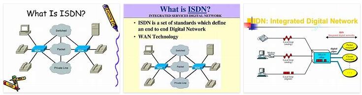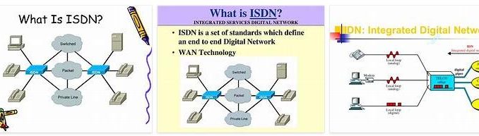
According to AbbreviationFinder.org, the ITU-T (CCITT) defines the Integrated Services Digital Network (ISDN or ISDN in English) as: a network that comes from the evolution of the Integrated Digital Network (RDI) and that facilitates end-to-end digital connections to provide a wide range services, both voice and other types, and which users access through a set of standardized interfaces. It was defined in 1988 in the CCITT Red Book. Before ISDN, the telephone system was seen as a form of voice transport, with some special services available for data. The key feature of ISDNis that it integrates voice and data on the same line, adding features that were not available in the classic telephone system. It can then be said that the ISDN is a network that proceeds by evolution of the existing telephone network, which by offering end-to-end digital connections allows the integration of a multitude of services in a single access, regardless of the nature of the information to be transmitted. and the Terminal equipment that generates it. In the ISDN studioso-called reference points have been defined that serve to delimit each element of the network. These are called R, S, T, U and V, U being the one corresponding to the pair of copper wires in the telephone loop between the exchange and the user’s home, that is, between the exchange and the network termination TR1.
Interfaces and Functions
We can divide ISDN into two classes according to bandwidth: narrowband ISDN and broadband ISDN.
Narrowband ISDN
The User Accesses defined for Narrowband ISDN allow communication at speeds of 64 Kbps, or groups of this speed. Due to the transmission and switching structure of ISDN, digital techniques, the integrity of the information is assured. Logically, this integrity allows secret communications or at least more immune to unwanted eavesdropping. On the other hand, digital techniques allow signal processing so that the transmission of information does not suffer degradations due to distance or external disturbances, noise, thus ensuring a “cleaner” information from errors. It is also an added advantage the possibility of sending small messages in the “call” to indicate special situations, sending texts such as: ”
A user can contract two different types of service with the telephone provider according to their needs:
- Basic access or BRI (Basic Rate Interface)
Basic access, also known by the acronym BRI (Basic Rate Interface), consists of two 64 kbps full-duplex B channels and one 16 kbps full-duplex D channel. Then framing, syncing, and other extra bits give a basic access point full speed of 192 kbps. 2B + D + signaling + framing This is the type of service that fits the needs of individual users.
- Primary access or PRI (Primary Rate Interface).
Primary access, also known by the English acronym PRI (Primary Rate Interface) is intended for users with higher capacity requirements, such as offices, companies with digital PBX or local network. Due to differences in digital transmission hierarchies used in different countries, it is not possible to agree on a single data rate. In the United States, it usually has 23 type B channels and one 64Kbps D channel, reaching a global speed of 1536Kbps. In europe the PRI consists of 30 B channels and a 64Kbps D channel, reaching an overall speed of 1984Kbps. In the second case, the B channels can also be grouped as 5 H0 channels or one H12 channel. This is the type of service contracted by entities with great demand.
ISDN broadband
This new network is basically the same as the current ISDN, with the difference that the minimum speed at which it works will be 2Mbps, and can reach 100Mbps. These speeds make it possible to greatly increase the number of services that the network will offer. To achieve these characteristics, broadband ISDN makes use of ATM network technology. A wide variety of applications for this technology are also being developed, including high-definition digital cable television services.
Services
Carriers
- Circuit Mode: these are the functions that are needed to establish, maintain, and close a switched circuit connection on a user channel. This function corresponds to the control of a call in existing circuit-switched telecommunications networks.
- Packet mode: these are the functions that are needed to establish a circuit switched connection in an ISDN packet switched node.
-Virtual Call Bearer Service. -Permanent Virtual Circuit Carrier Service.
Teleservices
- 7 kHz telephony
- Facsimile Groups 2 and 3 Facsimile Group 4
- Teletex, Videotex, Videotelephony.
- Supplementary
-Closed group of users. -Identification of the calling user. -Restriction of the identification of the calling user. -Identification of the connected user. -Restriction of the identification of the connected user. -Identification of call waiting. -Direct dialing of extensions. -Multiple subscriber numbers. – Abbreviated dialing. -Conference for three. -Call forwarding. -Call transfer within the passive bus. -Pricing Information.
Terminal Adaptation
Terminal (AT) adapters that perform the following functions are used to connect non-ISDN devices to the network.
- Speed Adaptation (AV)
- Signaling Conversion (CS)
- 25 conversion (AV + CS)
- Physical interface conversion.
User-Network Interface
To define ISDN user access requirements, it is very important to understand the advance configuration of user equipment and the required standard interfaces. The first step is to group functions that may exist on the user’s computer.
- Reference Points: conceptual points used to separate groups of functions.
- Functional groupings: certain finite arrangements of physical equipment or combinations of equipment.
Terminal equipment is the subscriber equipment that uses ISDN. Two types are defined. Terminal Equipment Type 1 (ET1) are devices that support the standard ISDN interface. For example: digital telephones, integrated voice / data terminals, and digital fax machines. Terminal equipment type 2 (ET2) contemplates the existence of non-ISDN equipment. For example, host computers with an X.25 interface. Such equipment requires a Terminal (AT) adapter to connect to the ISDN interface.
Functional groupings
Functional groupings are elements that develop a function, in this case they correspond to equipment or elements thereof, either of the Client or of Central.
- – Central Termination, located in the Switching Central, is responsible for maintaining User Access. It makes the connection of channels, supports the user signaling and the sending of information in packet mode.
TL.. – Line Termination, located in the Central, is in charge of the transmission aspects. Convert the binary code to the line code used. Control the timing of Access. This functional grouping is linked to the CT forming a cluster.
TR1. – Termination of Network No. 1, is the first element in the Customer’s domicile and obligation of the company operating the service, in Spain Telefónica. It allows synchronization with the equipment connected next, controls the connection with the Central, adapts the line signals to appropriate codes for the connection of the equipment, allows remote verification, being able to evaluate the quality of the link.
TR2.- Network Termination No. 2, performs control functions in the Customer’s installation: treatment of signaling, multiplexing of information channels, possible local switching (switchboard), traffic concentration and maintenance of the user’s installation.
ET1. – Terminal Equipment No. 1, is the ISDN Terminal Equipment, prepared for packet mode signaling and information channel management. Examples include ISDN telephones, computers Video Phone, PC Cards, among others.
- – Terminal Adapter, it is an ISDN equipment that has the ability to adapt interfaces. Converts signals from other non-ISDN equipment to signals suitable for the corresponding interface (“S” interface).
ET2. – Terminal Equipment No. 2, are non-ISDN equipment that can be connected through a non-standardized ISDN interface to the Network. Fax Groups 2 and 3, Analog telephones, modem.
Reference points or interfaces
Reference Points are interfaces between functional groupings and can be Real or Virtual. Virtual reference points are not accessible, or in some cases they coincide with another Interface.
- – represents the separation between the switching and transmission functions in the Central. It is a Virtual interface since TL and TC are joined on the Central Public Line Board.
- – represents the transmission characteristics on the line, in such a way that it specifies the format of the frame in it, the possible codes, signal levels, the allowed disturbances (attenuation, noise). It provides the TR1 with the possibility of synchronization, activation, and serves as a transport to the Access.
- – represents the separation between the line transmission and the transmission at the Customer’s home. It is a Transmission point that can coincide with Point “S”.
- – represents the physical connection interface of the ISDN Terminal equipment, and defines the frame structure, D-Channel management, synchronization and transmission characteristics.
- .- represents an interface not standardized in ISDN, and requires a TA so that the corresponding equipment can connect to the Access.
In Basic Access, points S and T correspond to the same interface, being called interface S. Thus, the connection of a Terminal equipment is made directly to TR1, by means of a specific installation configuration (Bus). A TR2 can be connected but it must implement an S interface in the connection. In the Primary Access, a TR2 will be connected to transform the T interface into an S interface, allowing the connection of ISDN Terminal equipment. In the case of teams that manage the 30 communication channels, Videoconference of high quality, this is connected to the T interface, since the equipment will perform the functions of TR2. On the Central side, the TL and TC groupings are always included in the corresponding line card, so the V interface will not be accessible. The U interface can be adapted to other signals by means of the appropriate transmission equipment, thus ensuring greater coverage (multiplexers).
Services support
- Points 1 or 2: (T and S) Basic Services.
- Point 4: (R) access to other standardized services. (X and V interfaces).
- Points 3 and 5: Access to Teleservices
- 3 ISDN terminals
- 5 ISDN terminals
The reference point T (Terminal) corresponds to the minimum ISDN network termination of the client computer. Separates the network provider equipment from the user equipment. The S (system) reference point corresponds to the ISDN Individual Terminals interface. Separates the user terminal equipment from network related communication functions. The R (ratio or rate) reference point provides a non-ISDN interface between non-ISDN compliant user equipment and adapter equipment.